Russia


City


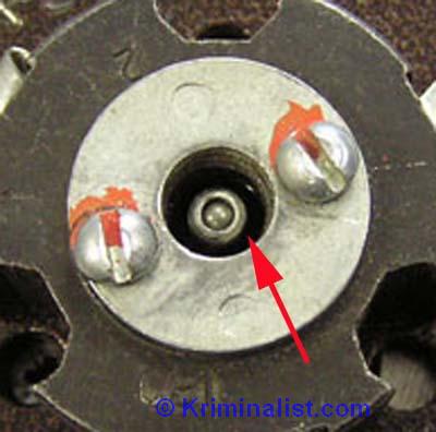
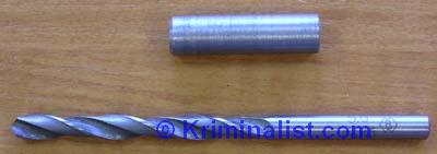
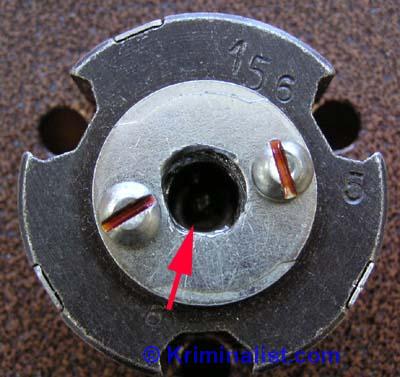
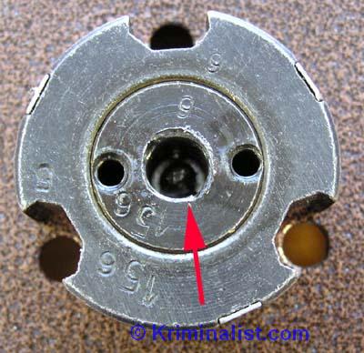
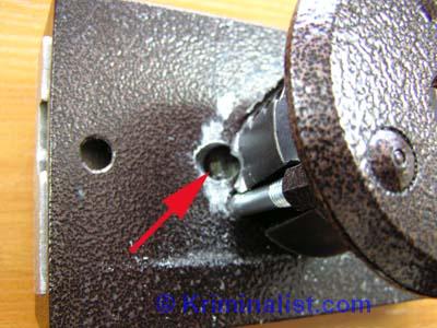
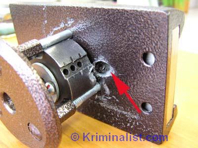
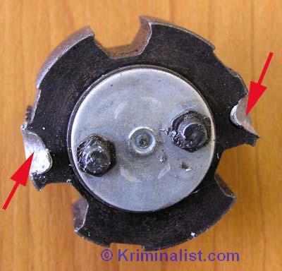
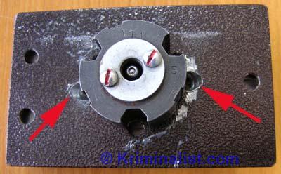
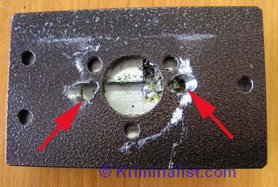
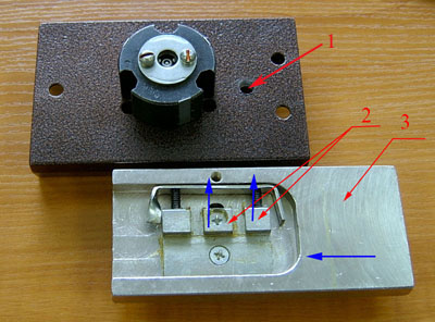
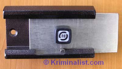
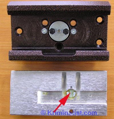
Photo 8. View of the cylinder mechanism of the Barrier locks. The red arrow indicates the guide post inside the cylinder. The stand is protected from drilling with a steel ball. The stand is not only a guide for the prickly, but also prevents the pins from falling out of the cylinder. To drill the rack, a guide tube with an outer diameter of 8 mm and an inner diameter of 5 mm was used. The stand was 'damp', so a conventional drill R6M5 with a diameter of 5 mm was used (photo 9). Device for criminal unlocking Photo 9. View of the guide tube and drill used to drill the cylinder post. To unlock the lock by drilling the rack, the following steps were performed: 1. By drilling into the rack from the side, remove the steel ball. 2. A guide tube was inserted into the key hole and a rack was drilled through it. 3. The guide was pulled out sharply. Under the action of the springs, the code pins (steel balls) poured out of the cylinder. 4. Using tweezers and a wire hook, the support pins and springs were removed from the cylinder. 5. Opened the lock with a key from another Barrier lock. Photo 10. View of the cylinder mechanism after drilling. A red arrow indicates that there are no strut or pins in the cylinder. Photo 11. View of the cylinder with the cover removed after drilling the rack. It was not difficult to remove the steel ball from the rack and drill the rack. This procedure took no more than two minutes. I had to tinker with removing the support pins and springs from the cylinder. The total time for unlocking the lock using this method was 23 minutes. This unlocking method is suitable for both Barrier 2 and Barrier 2M locks. The second method is to drill out the mounting screws of the cylinder mechanism. Photo 12. The red arrow indicates the place of drilling into the fastening screw of the cylinder mechanism. Drilling is done at an angle and the shield is not obstructed. Photo 13. Same as Photo 12, but we drill the second fixing screw. Photo 14. View of the cylinder mechanism, after drilling the attachment points. The red arrows mark the cylinder attachment points. Photo 15. This is how the castle looks after the above procedure. The essence of the technique for unlocking the lock in this way is as follows, having drilled out the attachment points of the cylinder, pull it out of the lock body (it is enough to move it by 3 mm) and through one of the holes we move the bolt to the 'unlocked' position. We managed to open the lock in this way in 3 minutes. 15 sec. Photo 16. View of the lock after removing the cylinder mechanism. Red arrows indicate the attachment points of the cylinder mechanism. The third method (applies only to Barrier 2) - drilling a hole in the lock body in order to raise the deadbolt lock and move the deadbolt. Photo 17. View of the castle Barrier-2. Red arrows and numbers indicate: 1 - hole in the lock body, which must be drilled in order to unlock the bolt and move it to the unlocked position; 2 - projections on the inner side of the crossbar, which must be acted upon through a drilled hole in the lock body, the direction of the force application is indicated by blue arrows; 3 - deadbolt, the blue arrow shows the direction of movement to the 'unlocked' position. The manufacturer of the Barrier locks made an upgrade of the Barrier 2 model, changing the handle and the deadbolt unlocking system, as I think in order to eliminate the possibility of criminal breaking the locks in the way described above (see method three). The new model was named Barrier 2M (modernized). What do we see in practice? But in practice, it turned out that the lock is opened much easier than in the Barrier 2 model. How exactly, read the fourth method below. Photo 18. View of the lock Barrier 2M with a rotary handle. Photo 19. The construction of the castle. The red arrow shows the deadbolt locking mechanism. To open the lock, it is enough to drill one hole by drilling the part indicated by the arrow.
 Blog
Blog
 map
map